I thought this post was going to be called “Tender final details” until I looked at the photos. Don’t the side sills look plain? That’s what I thought too, and it sent me scurrying to the reference material. So, there’ll be another post tomorrow. It turns out the handrails and lift bars are only the penultimate details.
The coupler lift bars look like they are very far in, but they’re supported by a good photo of sister engine #624’s backside. With the boiler stays, I discovered that a plastic nut-bolt-washer casting actually adds a surprising amount of strength to what ought to be a very weak joint. So, I fixed the cut lever stanchions in place with some too.
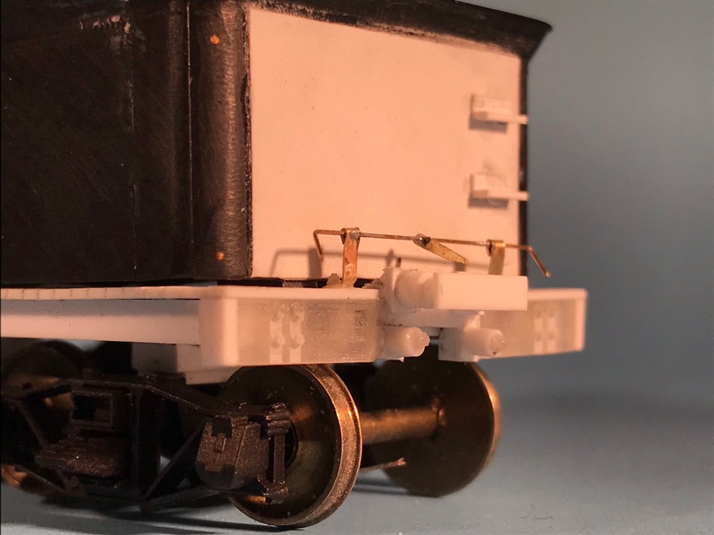
The coupler cut lever is fashioned out of phosphor bronze wire and brass strip. NBWs pass through and into the end beam, helping to secure this vulnerable part from breaking off. 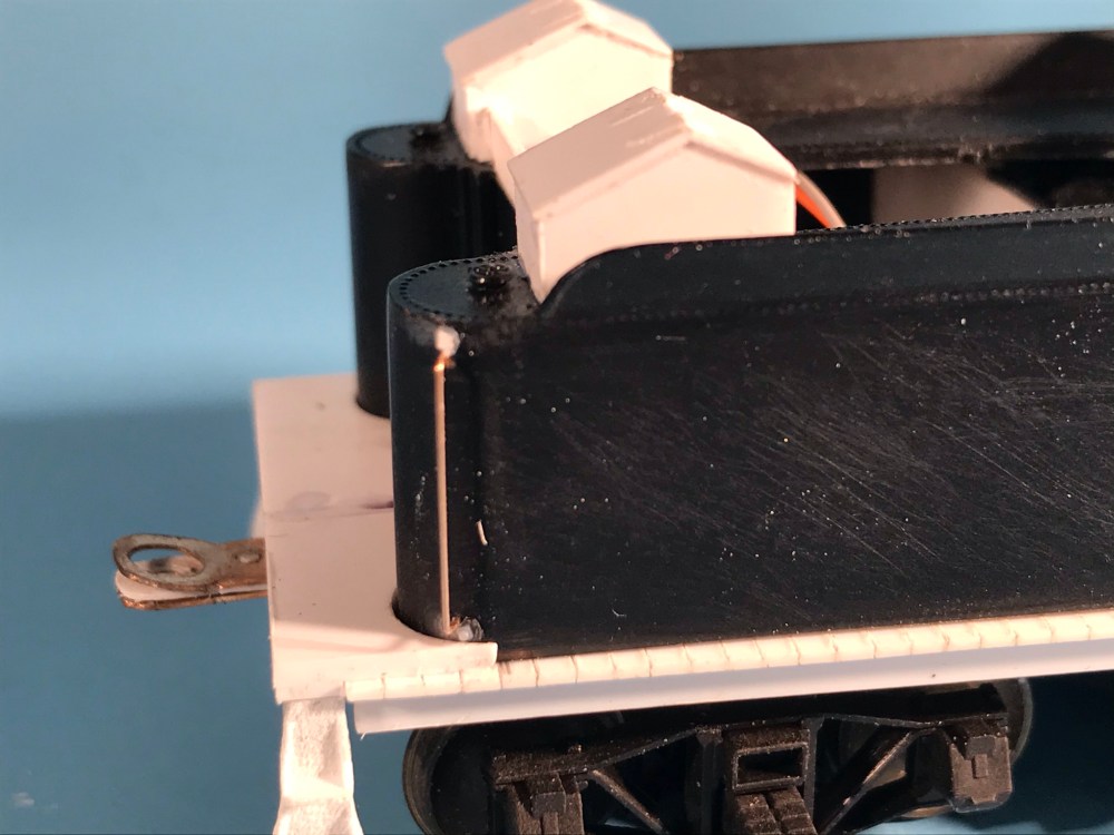
The handrails are simple .010″ phosphor bronze wire. NBW castings represent the ends of the fittings, but now that I think about it, I could easily print some grab iron ends to improve on such details.

I’m curious to learn what drilling set up-you are using for the brass and plastic holes? I assume some of this is done to parts before they are added to the model? But some of those holes are in pretty awkward locations – not the kind of thing your lathe or drill press makes easy.
It’s more art than science, Rob. For the boiler stays, I drilled the brass before installation, then drilled through those holes into the end beam. For the coupler cut lever, I glued them in place then drilled through both the bracket and the end beam at once. You’re right: it was awkward!