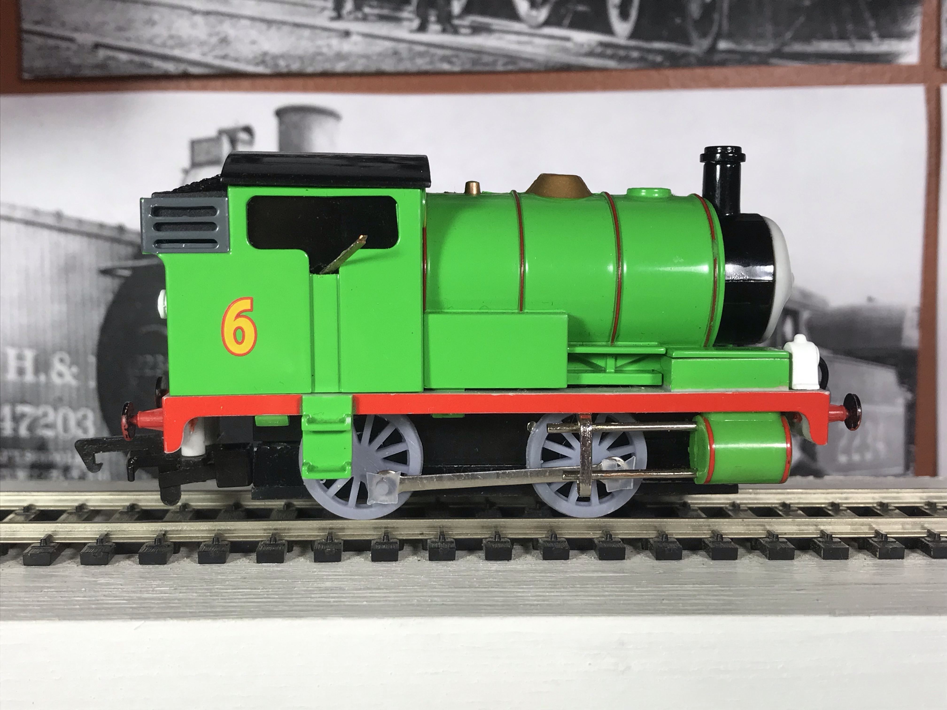
On disassembling Percy, the first surprise was how loose the connecting rods were on the crankpins. I’d read, and have probably reiterated, that the finest line is the one that separates running clearance from slop. I’d always imagined that where crankpins are concerned, it really mattered.
I’ve now tried four different crankpin sizes in Percy’s comically large connecting rod holes. They all worked. Thickening the crankpins up to just run in the bosses made no difference.
Then I thinned them down to 1/16″, which according to my calculations should allow the wheels to get 45 degrees out of phase. After being pushed for a few revolutions, the chassis did indeed bind. However, under power, it mysteriously ran fine! At all speeds.
I am aiming for about 1mm crankpins, and so, I printed a pair of wheels like that. Here the wheels should be able to get 60 degrees out of phase, and I would expect there to be all sorts of trouble. However, it behaved no differently than the slightly thicker 1/16″. Of course, the rear wheel was obviously lagging, and probably contributed little to the traction. Cosmetically, the connecting rod was often far from horizontal. However, and this is key, it didn’t bind under power.
Percy, you really are a very useful engine!
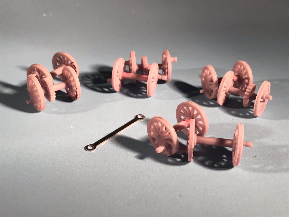
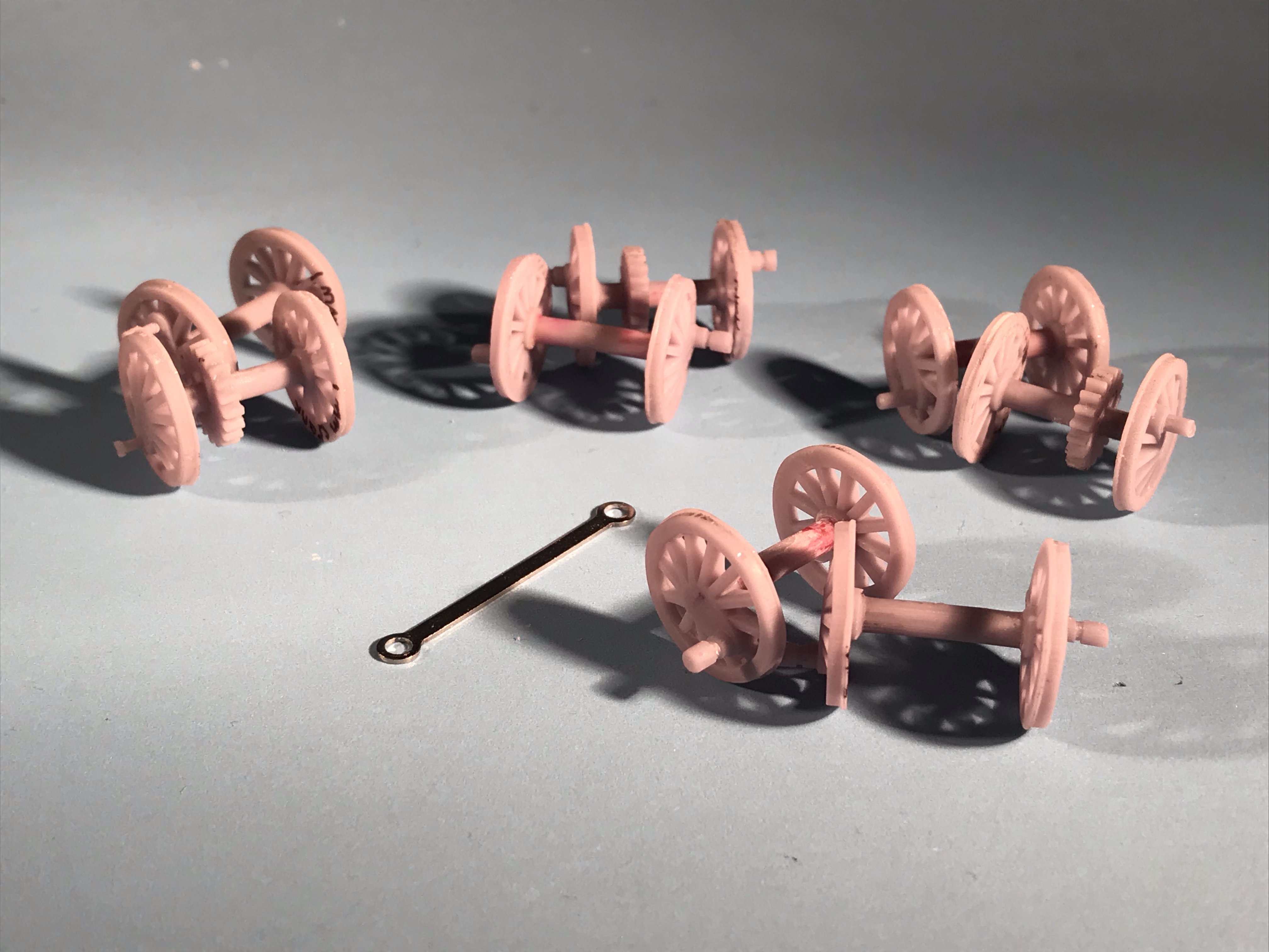
Four different crankpin sizes, and they all work under power. Clockwise from top left: 1mm (.039″), .093″, 1/16″ (.062″) and the original .083″ 
With 1mm crank pins, the rear wheel gets noticeably out of sync, and the connecting rod loses its horizontal aspect. However, it still works!

Interesting findings: is it as simple as “roomy connecting rod crank pin holes work”? A whole bunch of questions come to mind:
Can the centre of the holes in roomy fitting connecting rods move concentrically with the centre of the crank pin? or on an elliptical orbit? Or on a non-concentric orbit with only one side/arc of the hole in the connecting rod bearing on the pin? Or do they do all of those some of the time?
I guess a benefit of quartering is that it creates limits on how the connecting rod holes can wander around the pins when the whole assembly is in motion?
Is the fit mostly a factor in wear?
Do the drive rods also work with a roomy fit?