I had thought, or maybe hoped, that that the water tower was going to line up to the left (north) of the joist. However, there is some rule about joists, that places them exactly where they are least convenient, and when rulers and pencils got involved, it emerged that the best place for the water tower is directly on the joist. Second best is to the right of the joist. However, when we peak under the layout there, we find that space is filled with hefty slides that drive the first two turnouts on the layout.

I can barely get my fingers in there, much less imagine connecting levers for the spout and the float. So, I spent an evening thinking about how to make a mechanism that plugs together.
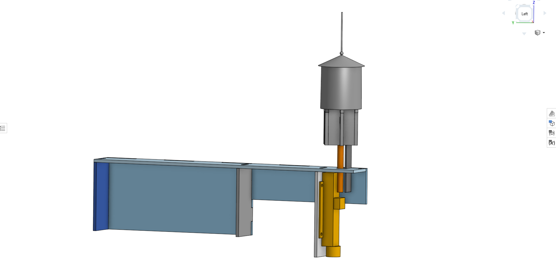
I landed on a pair of plungers – a round one to drive the float and a flat one to drive the spout. The idea is that these should be heavy enough that gravity keeps them engaged with the linear actuator and a pulley. Then I can feed the business end of the whole mechanism in on a stiffened piece of plywood, and screw it in at the near end where there is space to swing a screwdriver.
Well, that’s the theory, anyway.