Like most Canada Atlantic locomotives, #622’s pilot was decorated with three hoses. Sure one is for brakes, but I have no idea what the others were for. Even some (but not all) of the switchers had at least one extra hose. More modern locomotives might have a signal and a steam line; usually the signal line would be beneath the brake hose, while the steam line would be on the opposite side. One of the extra hoses could be a signal line, just not yet moved to a standard location. If the third hose was steam – it does appears to have a different end – what was it for? Canada Atlantic passenger trains were heated with coal, either in stoves or Baker heaters.
Except for more accurately modelling the connections, it probably doesn’t matter what the hoses were for. I modelled them with some wire and insulation. Two different sizes of wire required two different colours of insulation (though for the same nominal wire gauge). Insulation also helps make the elbow connectors and some of the other pipe fittings. Stop cocks are modelled with slivers of still finer wire.
I cut the pilot deck with the Cricut; when compared to the tribulations of getting #10’s pilot deck symmetrical, I felt I was cheating. The pilot beam itself includes some pockets. the edges of which were too thin for 3D printing. I cut chads of styrene (this time by hand) and cemented them in place with Tamiya plastic weld.
I turned the flag holders on the lathe; they include holes for flags.
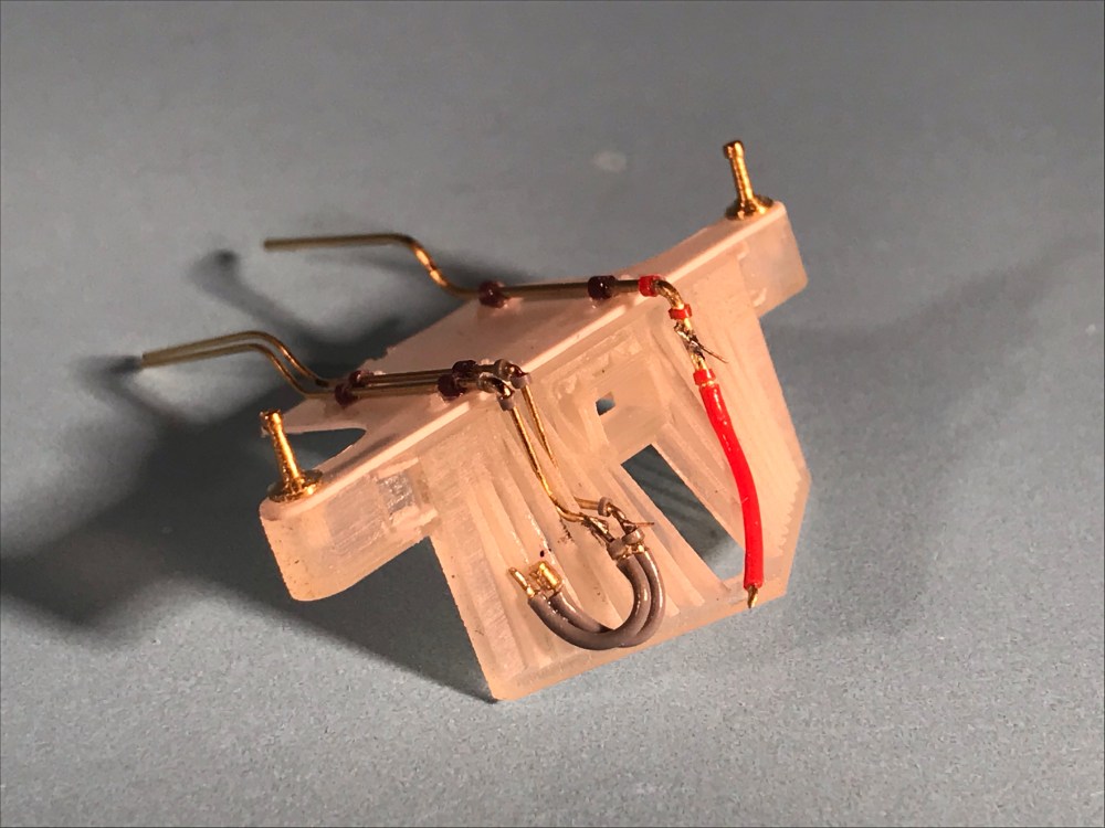
Air and steam (?) hoses are made from wire and insulation. The ends of the wires pass over the cylinder saddle and I will bend them down after painting and final installation 
I’m hoping the bits of insulation on the pilot deck, together with the NBWs will read like pipe brackets once painted.

Nice work on the flag holders. Did you print the NBWs on the Mars?
Thanks Andrew. No, the NBWs are Grandt Line. If I had printed them, I would have printed full pipe brackets instead. Indeed, I’m pondering whether 623 will have the whole pilot deck printed.
The biggest would be for air.
Are the other two on the opposite side?
I would guess one for steam, and possibly the third: main reservoir?
1st generation diesels had the following:
Sand, signal (some not all) actuating (releasing loco brakes when making train line application), independent (loco brakes) and main reservoir.
Obviously a steam locomotive wouldn’t need a actuating, or independent line so that leaves the main res as a possible guess. A main res. line would make sense if other locomotives had it. Its cold up north and with 2 engines pumping on the air it might help air up faster
I could be completely wrong…
Craig
Nice conjecture, Craig. To add to the mystery, it looks like there are only two lines on the back of the tender! https://flic.kr/p/sb9Pc