Eight years! I am amazed to learn that I started pecking away at the fascia-mounted turnout control problem eight years ago. Well, this week marks the conclusion of the design phase, as I finally have a version I believe will be robust and easy to install.
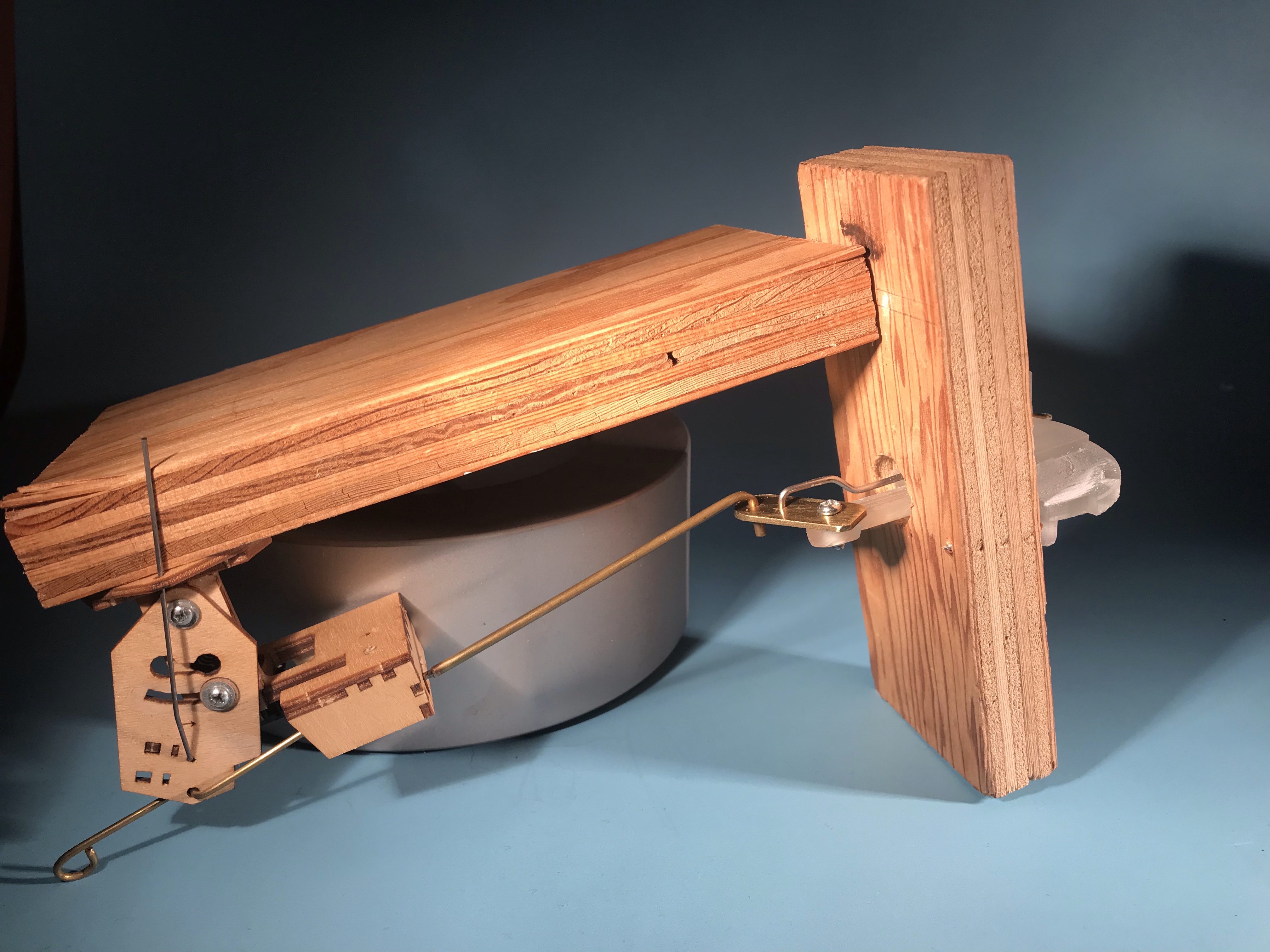
This is a minor improvement over the Mark II design. Aside from printing in the Elegoo ABS-like resin, I’ve beefed up many of the thicknesses and added a second screw. This latest version feels solid, and moves easily to drive a FastTracks Bullfrog, which is standard for Pembroke.
The two levers are brass for added strength. All I have to do now is decide which, if any, switches need to be locked.


Are your turnouts stub switches?
No, it’s hard to tell from photographs, but it’s likely they should be. I went with split switches for Porto:87 demonstration purposes.
I was inspired by your original 2014 design and cobbled together my own versions from stock – these will be much more elegant! I’m not quite clear how you plan to use locks – will there be holes for a padlock in the semicircular horizontal plate, or in the quadrants that enclose the lever extension? Great work, I’m very pleased to see these ripen.
Thanks Jeffrey, I’d love to see what you came up with! I need to do more research, but I believe the locks were on the upper part of the lever and stopped it from dropping into the housing. If you can’t lift the lever, you can’t throw the switch.
You’ve seen it and commented on it, but that was 8 years ago so I can understand that you’ve forgotten!
https://forum.mrhmag.com/post/middle-school-model-rr-cranks-and-levers-12199244?pid=1330924401
A postscript to this (detailed in another blog post) is that I elected to “postpone” the use of these fascia mounted levers because center-spring turnouts were so convenient. But if you “go into production” on your units put me down for a bunch, I’m about to start a new railroad and I still think it’s a great solution.
Oh, yes, I remember now! The sad thing is that unfortunately the lever itself needs to be metal or else it won’t survive a bump. Maybe they could be printed at Shapeways. Once I’m ready, I’ll upload them and see if they’re printable.
I’m now at a point where this is becoming necessary to figure out as well. My thought was a latch similar to a tool box that is normally down over the projecting tab with a hole in it to attach a lock. Remove the lock, flip up, pull and twist to change the direction of the points. A spring would pull it back in once turned back 90 degrees. Doing this is resin seems fragile but could be cut, folded, and soldered together quite easily. I will only nine total. Time to bust out the sketchpad if this description isn’t clear.
Sounds interesting but definitely needs a sketch! For me, the lift and turn action is important.