With Percy now coated in primer, it is easier to see and comment about how that single big print went. Truthfully, it was two prints because the first one had the cylinders too high. While I wouldn’t consider it a failure, the single big print was not the best decision.
I knew I was in trouble when I started having to add supports for the bell and the overhangs on the steam dome, sand box, stack and headlight. These supports terminated on the top of the tank, or worse, on the front of the cab where they would prove to be difficult to clean up. However, I pressed on, as I usually do, just to see what would happen.
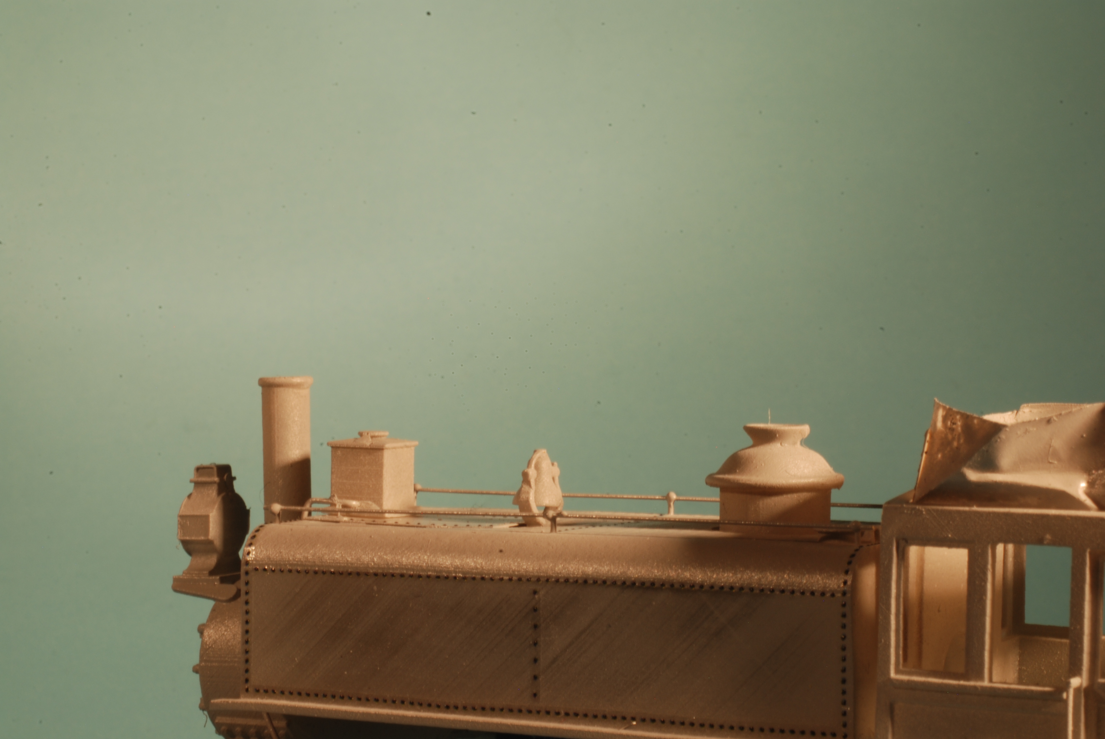
I printed the shell on a 45 degree angle, which was faintly visible on the sides of the tank, and easily sanded off. However, there is noticeable stepping on the back, front and top faces – those that were actually at 45 degrees. This is because the 47 micron pixel size doesn’t divide evenly by the step size, meaning that every so often, an extra layer must be printed to meet 45 degrees. This is something I may be able resolve by changing the layer depth.
I was impressed that the bell printed in place so nicely, and the arm survived a lot of handling before I finally knocked it off while fixing a divot that appeared when the contact cement I used for fixing the weight melted the top of the tank. I was even more impressed that the .015″ handrail stanchions atop the tank lasted through all the handling. I’m pleased with my decision to form the handrails themselves from wire sitting in tiny drops of epoxy atop each stanchion.
Anticipating that I would have to true up some of the flat surfaces, I left the rivets off. Besides, they’re a bit of a nuisance to form in CAD, and installing Archer rivets is fun. I also left the sanding lines off because it would be easier to form them from soft wire than to model them in 3D.
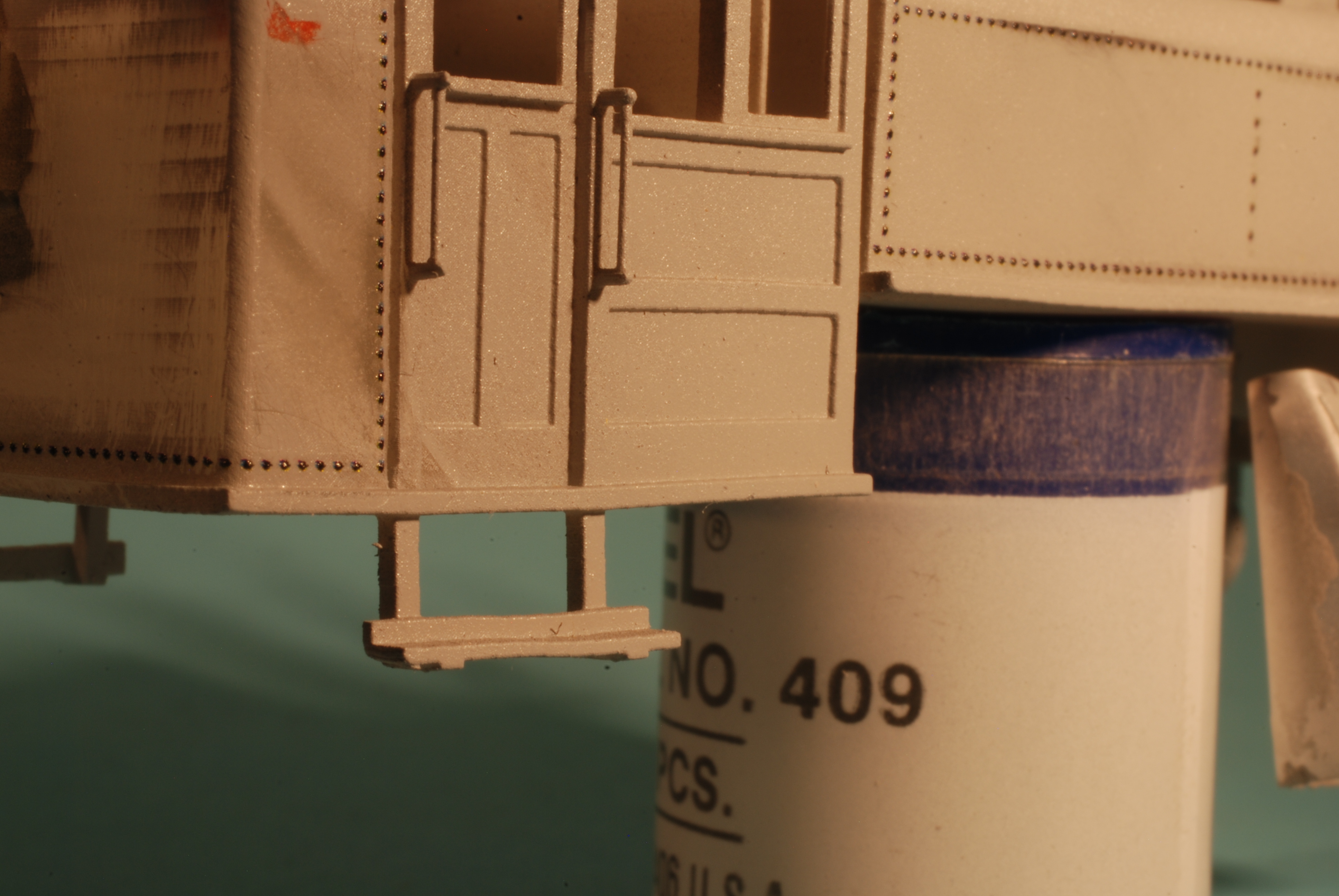
The cab handrails were only .012″, but surprisingly robust. One did break during handling, and I replaced it with .015″ styrene.
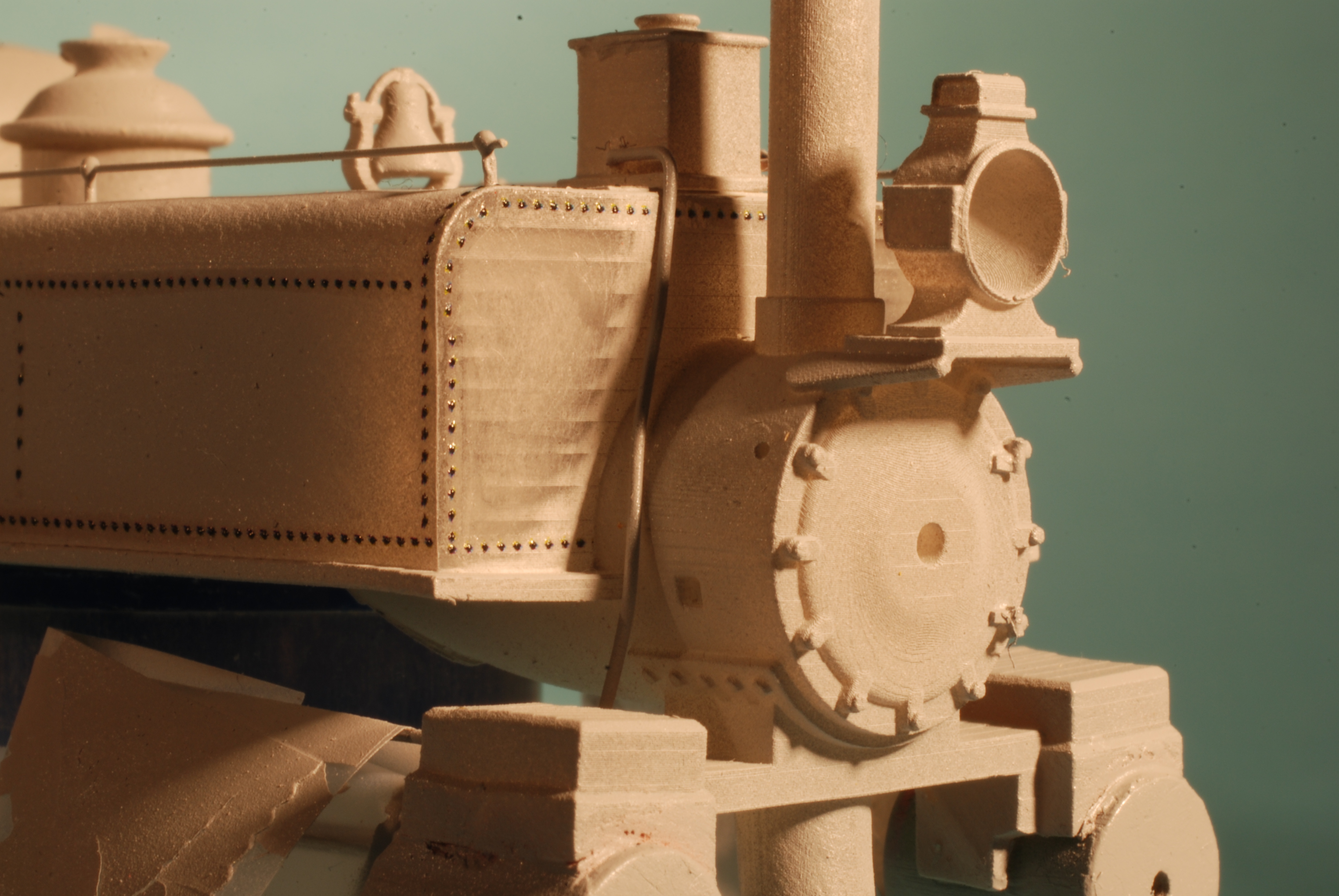
There were some notable support failures during printing. The bottom rear of the cab, which was almost the first layer to print, failed at the corners; we have a slight bow there as a result, and the bunker needed extra sanding. The cylinder saddle was also under-supported, and I wound up building it back up with filler. Other bows are harder to explain, like the forward corner of the cab, and the whole back of the tank. These surfaces were well supported.
The back of the tank is only a few scale inches from the front of the cab, and this proved very difficult to coat with primer or paint without depositing too much paint nearby. I left the air compressor off to make painting easier, and in retrospect, I should have done the same with the tank.
Overall, printing a single big piece meant that I was reluctant to spend another 7 hours waiting for a replacement shell, and thus corrected most problems the old fashioned way. As usual, I learned in the process, but I wouldn’t print this model as a single piece again.

I’ve made a few bodies for the N scale Percy to model HOn30. This one is the SD Warren locomotive. https://photos.app.goo.gl/tUNmHBdt5GosKJwT9
Here is another HOn30 Percy work in progress. https://photos.app.goo.gl/ZKV1qGRXYpXJ3gqg6
Wow, those are really cool!
Like you said, with the proper angle some of the banding will go away. On that generation of screen/Z axis combo I made things in as many parts as I could to get the pristine top surfaces. In hindsight there is ground to be had by rolling the model at a compound angle. You might be up against the limits of the screen dimensions with Percy but for smaller items try it out and you’ll likely be surprised. Since none of the OEM slicers I use work very well models are loaded into Prusa slicer and rotated to “best surface finish” saved as .stl w/supports and finally saved to the relevant format in the native slicer. It uses three or four times the resin (supports) and takes up way more space than when you’re used to filling the build plate with home made supports but the overall quality is higher on any model with flat surfaces at slight angles to one another.
Thanks Andrew, I shall have to try this.
I was and still do print mostly everything perfectly flat. Doing this if there are any build lines they are usually on top and can be sanded out. But when you switch to a round locomotive boiler I found it needs to be at an angle. I have been doing everything at 23 degrees, but each machine is different. I use ChiTuBox to add supports and slicing. I have never even once used auto supports. I place each and every support one at a time. Over time I know just where they need to be to get a good print on the first try. I’m only using Sketchup to draw and a few of my designs are here: https://www.thingiverse.com/chris33333/designs The files can be resized to any scale.
Here is a close up of the SD Warren in primer. A few supports along the rear roof have been removed, but you can see most are still there. In primer it makes it easier to see as resin is slightly translucent.
Chris
Also you mention 47 microns. This chart is set up for that depending on what layer thickness you use. https://photos.app.goo.gl/VqrrDHHWJCTJoGLi9
I use 0.05mm layers so I don’t get any sagging on open areas. I started with an Anycubic Photon that was 47 microns. I now use a Phrozen Sonic Mini 4K that is 35 microns (pixel size of the screen). It is hard to tell the difference between 35 and 47 to the naked eye.
If you still get banding it may have to do with the lead screw of the Z rail. The banding in this HOn30 boxcar:
https://photos.app.goo.gl/2SCiazohtsk9JwWw5
Was fixed by changing the screw:
https://photos.app.goo.gl/TRGHcyMuygBwizUcA
And this was the result:
https://photos.app.goo.gl/eYVM2J62ZtqBDQuQ6
Sorry for all the links.
Chris